devices.esphome.io
H801 RGBW LED controller
H801 RGBW LED controller
Device Type: lightElectrical Standard: globalBoard: esp8266
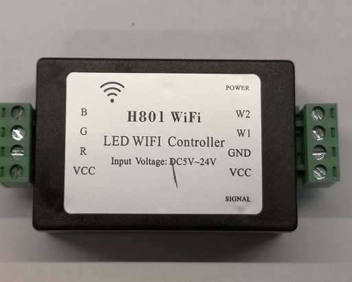
The H801 is pretty affordable and easy to hack and adapt to your needs. It can be found on AliExpress and other sites. The board is based on an ESP8266EX chip.
It has 5 seperate PWM outputs (each driven by a DTU35N06 MOSFET rated for 106W max power), and can be used as a RGB / RGBW / RGBWW / RGBCT controller or configured with any combination of up to five individual monochromatic PWM lights. See A closer look at the H801 LED WiFi Controller for more details on the hardware.

Sample configuration
You can use the RGBWW and the ESP8266 Software PWM output components using below configuration:
esphome: name: h801light
esp8266: board: esp01_1m
wifi: ssid: !secret wifi_ssid password: !secret wifi_password
logger:api:ota:
output: - platform: esp8266_pwm pin: 12 frequency: 1000 Hz id: pwm_b - platform: esp8266_pwm pin: 13 frequency: 1000 Hz id: pwm_g - platform: esp8266_pwm pin: 15 frequency: 1000 Hz id: pwm_r - platform: esp8266_pwm pin: 14 frequency: 1000 Hz id: pwm_w1 - platform: esp8266_pwm pin: 4 frequency: 1000 Hz id: pwm_w2light: - platform: rgbww name: "H801 Light" red: pwm_r green: pwm_g blue: pwm_b cold_white: pwm_w1 warm_white: pwm_w2For RGBW
lights, the pwm_w2 output is not used (and can be removed):
light: - platform: rgbw name: "H801 Light" red: pwm_r green: pwm_g blue: pwm_b white: pwm_w1Flashing
Make your node in the ESPHome dashboard and compile/upload it. (if it
fails OTA it must be uploaded manually with your favorite ESP flasher,
e.g. esphome-flasher <esphome-flasher>{.interpreted-text role="ref"})
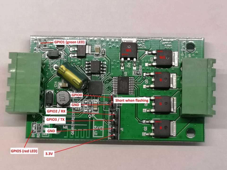
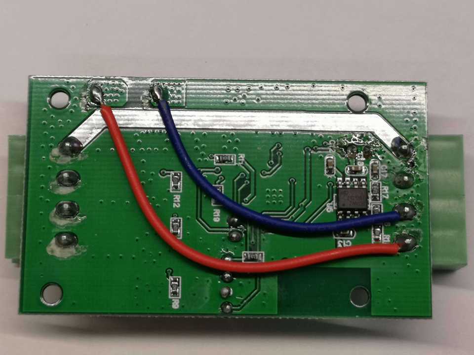
You will need to solder pins to the board inside the H801 (fortunately it\'s pretty roomy and not a lot of components or stuff in the way apart from the 2 wires on the back).
3.3V, GND, TX and RX (RX to RX and TX to TX) needs to be connected to your serial adapter, the two other pins must be shorted throughout the flashing process by a jumper or a breadboard cable. (Remember to remove it after flashing)

Front side of board with pins soldered on

Back side of the board (don\'t melt the blue and red wire when soldering)
Add A PIR(Motion) Sensor
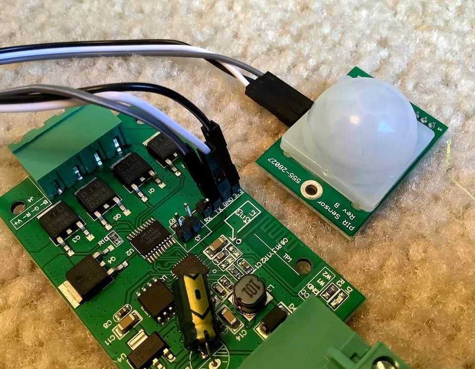
It\'s possible to use the header that was soldered on for flashing as an input. The example below uses the TX pin as a PIR motion sensor input:

H801 shown with PIR connected to header pins
The following can be appended to the YAML file for your H801 to configure the TX pin as a motion sensor input.
binary_sensor: - platform: gpio pin: GPIO3 name: "GPIO3-TX Motion" device_class: motionPinout
| Function | ESP Pin |
|---|---|
| R (PWM1) | GPIO15 |
| G (PWM2) | GPIO13 |
| B (PWM3) | GPIO12 |
| W1 (PWM4) | GPIO14 |
| W2 (PWM5) | GPIO4 |
| Jumper J3 | GPIO0 |
| RX | GPIO2 |
| TX | GPIO3 |
| LED D1 (red) | GPIO5 |
| LED D2 (green) | GPIO1 |